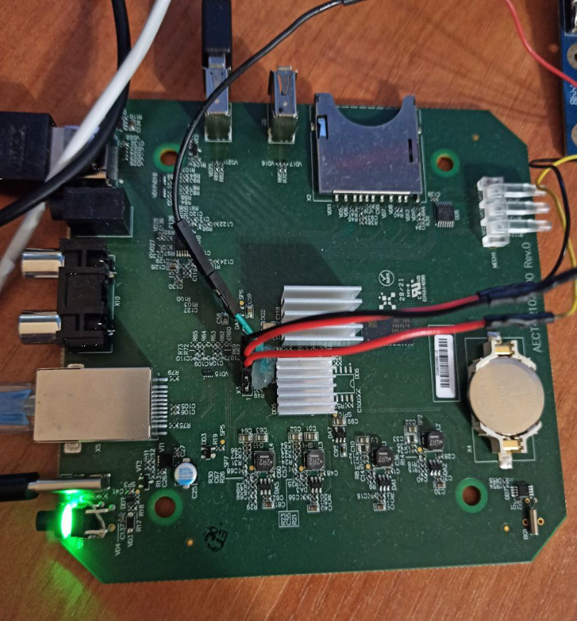
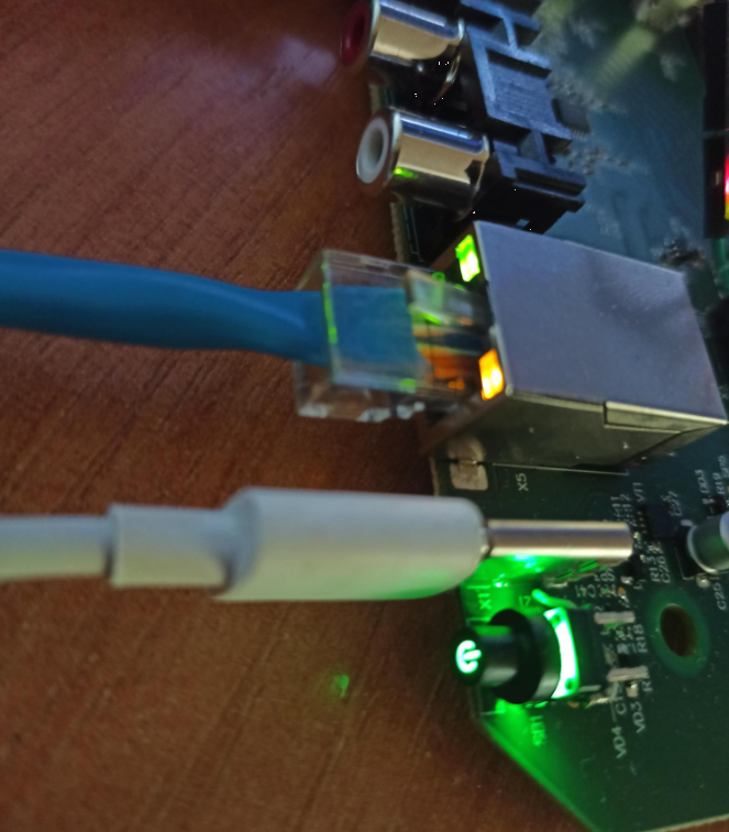
One of the previous projects was related to bringing up our newly developed board with the AmLogic s805x SoC CPU board. I will describe how the proccess of bringing up looks like, what was tested and also we will take a look how the AmLogic board flashing proccess is carried out for GXL platform (G12B and more recent are very similar). This is our board:
The first stage of bringup is to build image for reference board. Our case is p241. We took a113 sources for this. Build p241 reference sources:
Build image
1
2
3
4
5
6
7
# You need arm-linux-gnueabihf-gcc and aarch64-linux-gnu-gcc to be installed in system toolchains
$ sudo apt-get install zlib1g zlib1g-dev
$ source buildroot/build/setenv.sh
# Choose “mesongxl_p241_32_kernel49” // 37
$ ln -s aml-4.9 kernel/aml-3.14
$ ln -s aml-4.9 hardware/aml-3.14
$ make
After the proccess in complete everything will be at output/mesongxl_p241_32_kernel49/images with folowing parts:
- boot.img - kernel
- u-boot.bin - u-boot image
- rootfs.ext2 - rootfs
- gxl_p241_v2_1g_buildroot.dtb - dtb (for flashing to dtb partition using dtb.img)
Flashing image
Second step is flashing everything to MMC. The esiest way is to use AmLogic flashing tool called AmLogic USB Burning tool:
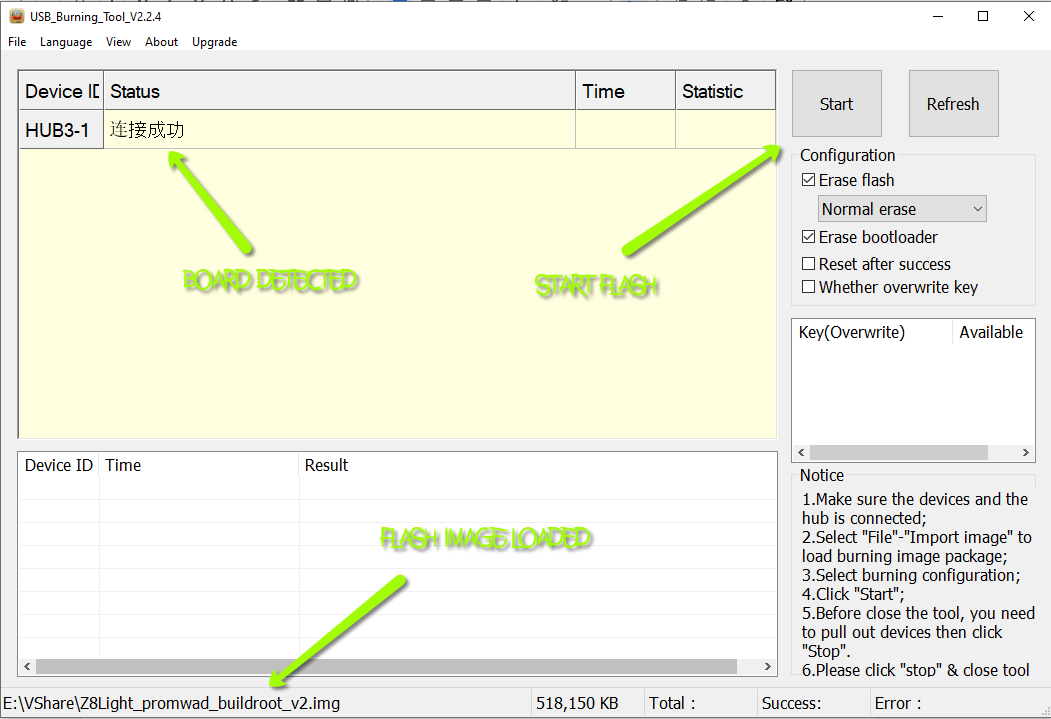
You must choise builded full image.
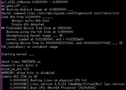
If everything fine you will see the the u-boot loading and kernel start after that
Control/Test USB LED’s
In our case everything was booted, but some part need aditional verifying. First of this is ethernet leds not work. How to blink them with kernel?
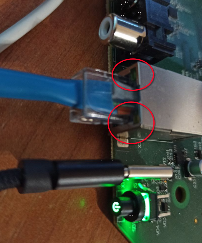
Thats pretty easy, change the ethernet LED’S with gpio state:
1
2
3
4
5
6
7
8
9
10
# It can be re enabled manually using control GPIO commands:
# GPIO (401 + 14) - green
# GPIO (401 + 15) - yellow

Z8# echo 415 >/sys/class/gpio/export
Z8# echo 416 >/sys/class/gpio/export
Z8# echo out >/sys/class/gpio/gpio415/direction
Z8# echo out >/sys/class/gpio/gpio416/direction
Z8# echo 1 >/sys/class/gpio/gpio415/value
Z8# echo 1 >/sys/class/gpio/gpio416/value
We set gpio direction and writing 1 to value.
Fix battery time with enabling DS1307 driver
Second problem is that battery clock is not working from start. Lets try to enable it. We are using DS1307 controller. So let’s apply the followting patch:
1
2
3
4
5
6
7
8
9
10
11
12
13
14
15
16
17
18
19
20
21
22
23
24
25
26
27
28
29
30
31
32
33
34
35
36
37
diff --git a/arch/arm/configs/meson64_a32_defconfig b/arch/arm/configs/meson64_a32_defconfig
index 8e7d5648501a..446e1973c554 100644
--- a/arch/arm/configs/meson64_a32_defconfig
+++ b/arch/arm/configs/meson64_a32_defconfig
@@ -593,3 +593,4 @@ CONFIG_ASYMMETRIC_PUBLIC_KEY_SUBTYPE=y
 CONFIG_X509_CERTIFICATE_PARSER=y
 CONFIG_CRC_T10DIF=y
 CONFIG_CRC7=y
+RTC_DRV_DS1307=y
diff --git a/arch/arm64/boot/dts/amlogic/gxl_p241_v2_1g_buildroot.dts b/arch/arm64/boot/dts/amlogic/gxl_p241_v2_1g_buildroot.dts
index bf77a30db461..ba45803a8552 100644
--- a/arch/arm64/boot/dts/amlogic/gxl_p241_v2_1g_buildroot.dts
+++ b/arch/arm64/boot/dts/amlogic/gxl_p241_v2_1g_buildroot.dts
@@ -1359,3 +1359,14 @@
        delay_control = <0x15>;
        ssctl = <0>;
 };
+
+&i2c0 {
+       status = "okay";
+       pinctrl-0 = <&a_i2c_master>;
+       pinctrl-names = "default";
+
+       rtc: rtc@68 {
+               compatible = "dallas,ds1340";
+               reg = <0x68>;
+       };
+};
diff --git a/arch/arm64/configs/meson64_defconfig b/arch/arm64/configs/meson64_defconfig
index 968ee40827bc..1367a6cebd19 100644
--- a/arch/arm64/configs/meson64_defconfig
+++ b/arch/arm64/configs/meson64_defconfig
@@ -617,3 +617,4 @@ CONFIG_CRYPTO_GHASH_ARM64_CE=y
 CONFIG_CRYPTO_AES_ARM64_CE_BLK=y
 CONFIG_CRC_T10DIF=y
 CONFIG_CRC7=y
+RTC_DRV_DS1307=y
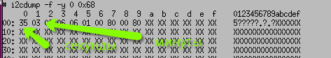
And now test with i2cdump:
1
i2cdump -f -y 0 0x68
Sound testing
We done it using speaker-test which is the part of the image
1
2
3
4
# via audio jack
Z8# speaker-test -c2 -D hw:0,0
# via hdmi SPDIF
Z8# speaker-test -c2 -D hw:0,1
Load testing
Let’s load the system at 100%. One of the effective ways is with bzip2:
1
Z8# (dd if=/dev/urandom | bzip2 -9 >> /dev/null &); (dd if=/dev/urandom | bzip2 -9 >> /dev/null &); (dd if=/dev/urandom | bzip2 -9 >> /dev/null &); (dd if=/dev/urandom | bzip2 -9 >> /dev/null &)
Let’s increase the load with multiple bzip proccesses and hw deconding playback:
1
2
3
4
5
6
Z8# (dd if=/dev/urandom | bzip2 -9 >> /dev/null &); (dd if=/dev/urandom | bzip2 -9 >> /dev/null &); (dd if=/dev/urandom | bzip2 -9 >> /dev/null &); (dd if=/dev/urandom | bzip2 -9 >> /dev/null &)
Z8# (dd if=/dev/urandom | bzip2 -9 >> /dev/null &); (dd if=/dev/urandom | bzip2 -9 >> /dev/null &); (dd if=/dev/urandom | bzip2 -9 >> /dev/null &); (dd if=/dev/urandom | bzip2 -9 >> /dev/null &)
Z8# gst-launch-1.0 filesrc location=videoplayback.mp4 ! qtdemux ! h264parse ! amlvdec ! amlvsink

## Verify with top
Z8# top
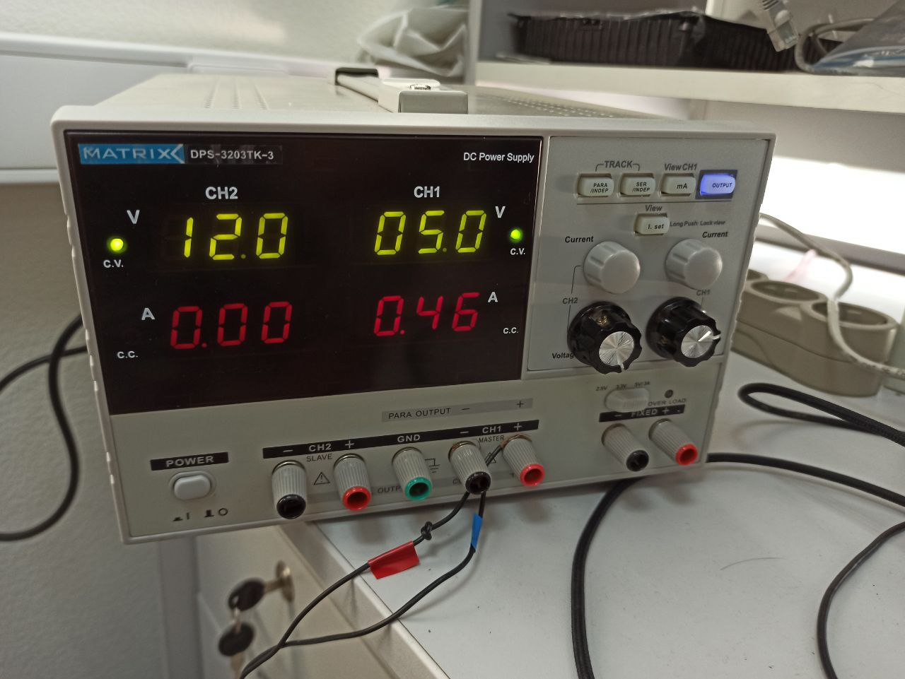
The maximum power consumption we got is 0.46A
Hardware accelerated decoding
Video h264 hardware accelerated
1
Z8# gst-launch-1.0 filesrc location=videoplayback.mp4 ! qtdemux ! h264parse ! amlvdec ! amlvsink
gst-launch-1.0 will start video decoding, so you can see video decoding on stream, use
1
Z8# killall chrome
Audio hardware accelerated
1
Z8# gst-launch-1.0 filesrc location=1.mp3 ! mpegaudioparse ! amladec ! audioconvert ! amlasink
Temperature measurements
1
Z8# cat /sys/class/thermal/thermal_zone*/temp
Play audio file
1
Z8# aplay -D hw:0,0 -c2 -f cd flower_ok.wav
Mounting usb drives
1
2
3
Z8# mkdir /media/flash
Z8# mount -t vfat /dev/sda /media/flash
Z8# cd /media/flash
HDMI tests
We just simply inseted monitor to verify that everything works :).