Exploring GStreamer and pipelines
Before proceeding to code review, let’s look at what we can do without it. GStreamer includes useful utilities to work with, in particular:
- gst-inspect-1.0 will allow you to see a list of available codecs and modules, so you can immediately see what will do with it and select a set of filters and codecs.
- gst-launch-1.0 allows you to start any pipeline. GStreamer uses a decoding scheme where a stream passes through different components in series, from source to sink output. You can choose anything as a source: a file, a device, the output (sink) also may be a file, a screen, network outputs, and protocols (like RTP).
Simple example of using gst-launch-1.0 to connect elements and play audio:
1
gst-launch-1.0 filesrc location=/path/to/file.ogg ! decodebin ! alsasink
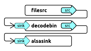
Filesrc will open file, decodebin - decode it, and alsasink will output audio.
Another more complex example of playing an mp4 file:
1
gst-launch-1.0 filesrc location=file.mp4 ! qtdemux ! h264parse ! avdec_h264 ! videoconvert ! autovideosink
The input accepts the mp4 file, which goes through the mp4 demuxer — qtdemux, then through the h264 parser, then through the decoder, the converter, and finally, the output.
You can replace autovideosink with filesink with a file parameter and output the decoded stream directly to the file.
Programming an application with GStreamer C/C++ API. Let’s try to decode
Now when we know how to use gst-launch-1.0, we are doing the same thing within our application. The principle remains the same: we are building in a decoding pipeline, but now we are using the GStreamer library and glib-events.
We will consider a live example of H264 decoding.
Initialization of the GStreamer application takes place once with the help of
1
gst_init (NULL, NULL);
If you want to see what’s happening in detail, you can set up a logging level before the initialization.
1
2
gst_debug_set_active(TRUE);
gst_debug_set_default_threshold(GST_LEVEL_LOG);
Note: no matter how many pipelines you have in your application, it is enough to initialize gst_init once.
Let’s create a new event-loop where events will be processed:
1
2
GMainLoop *loop;
loop = g_main_loop_new (NULL, FALSE);
And now we can start building our pipeline. Let’s name the necessary elements, in particular, the pipeline itself as the GstElement type:
1
2
3
4
5
6
7
8
9
GstElement *pipeline, *source, *demuxer, *parser, *decoder, *conv, *sink;

pipeline = gst_pipeline_new ("video-decoder");
source   = gst_element_factory_make ("filesrc",       "file-source");
demuxer  = gst_element_factory_make ("qtdemux",      "h264-demuxer");
parser   = gst_element_factory_make ("h264parse",      "h264-parser");
decoder  = gst_element_factory_make ("avdec_h264",     "h264-decoder");
conv     = gst_element_factory_make ("videoconvert",  "converter");
sink     = gst_element_factory_make ("appsink", "video-output");
Each element of the pipeline is created via gst_element_factory_make, where the first parameter is the type and the second is its conditional name for GStreamer, on which it will later rely (for example, when issuing errors).
It would also be nice to check that all components are found otherwise gst_element_factory_make returns NULL.
1
2
3
4
if (!pipeline || !source || !demuxer || !parser || !decoder || !conv || !sink) {
    // one element is not initialized - stop
    return;
}
We are setting the same location parameter via g_object_set:
1
g_object_set (G_OBJECT (source), "location", argv[1], NULL);
Other parameters in other elements can be set in the same way.
Now we need the GStreamer message handler, let’s create the corresponding bus_call:
1
2
3
4
5
6
GstBus *bus;

guint bus_watch_id;
bus = gst_pipeline_get_bus (GST_PIPELINE (pipeline));
bus_watch_id = gst_bus_add_watch (bus, bus_call, loop);
gst_object_unref (bus);
gst_object_unref and other similar calls are needed to clear selected objects.
Then we will name the message handler itself:
1
2
3
4
5
6
7
8
9
10
11
12
13
14
15
16
17
18
19
20
21
22
23
24
25
26
27
28
29
static gboolean
bus_call (GstBus     *bus,
          GstMessage *msg,
          gpointer    data)
{
  GMainLoop *loop = (GMainLoop *) data;
  switch (GST_MESSAGE_TYPE (msg)) {
    case GST_MESSAGE_EOS:
      LOGI ("End of stream\n");
      g_main_loop_quit (loop);
      break;

    case GST_MESSAGE_ERROR: {
      gchar  *debug;
      GError *error;

      gst_message_parse_error (msg, &error, &debug);
      g_free (debug);
      LOGE ("Error: %s\n", error->message);
      g_error_free (error);
      g_main_loop_quit (loop);
      break;
    }

    default:
      break;
  }
  return TRUE;
}
And now the most important thing: we collect and add all the created elements in a single pipeline, which was built through gst-launch. The order of addition is, of course, important:
1
2
gst_bin_add_many (GST_BIN (pipeline), source, demuxer, parser, decoder, conv, sink, NULL);
gst_element_link_many (source, demuxer, parser, decoder, conv, sink, NULL);
We should also note that this linking of elements works perfectly for stream outputs, but in the case of playback (autovideosink) requires additional synchronization and dynamic linking of the demuxer and parser:
1
2
3
4
5
6
7
8
9
10
11
12
13
14
15
16
17
18
19
gst_element_link (source, demuxer);
gst_element_link_many (parser, decoder, conv, sink, NULL);
g_signal_connect (demuxer, "pad-added", G_CALLBACK (on_pad_added), parser);

static void
on_pad_added (GstElement *element,
              GstPad     *pad,
              gpointer    data)
{
  GstPad *sinkpad;
  GstElement *decoder = (GstElement *) data;

  /* We can now link this pad with the sink pad */
  g_print ("Dynamic pad created, linking demuxer/decoder\n");

  sinkpad = gst_element_get_static_pad (decoder, "sink");
  gst_pad_link (pad, sinkpad);
  gst_object_unref (sinkpad);
}
A dynamic connection makes it possible to determine the type and number of threads in contrast to a static one and will work in some cases when it is required.
And finally, let’s turn the conveyor status into a playback:
1
gst_element_set_state (pipeline, GST_STATE_PLAYING);
And let’s run event-loop:
1
g_main_loop_run (loop);
After this procedure, everything needs to be cleaned:
1
2
3
4
gst_element_set_state (pipeline, GST_STATE_NULL);
gst_object_unref (GST_OBJECT (pipeline));
g_source_remove (bus_watch_id);
g_main_loop_unref (loop);
Choosing encoders and decoders. Fallbacks.
There’s more to tell about useful but barely mentioned things in the documentation: how you can easily organize a fallback decoder or encoder.
The gst_element_factory_find function will help us do this by checking if we have a codec in the elements factory:
1
2
3
4
if(gst_element_factory_find("omxh264dec"))
  decoder  = gst_element_factory_make ("omxh264dec",     "h264-decoder");
else
  decoder  = gst_element_factory_make ("avdec_h264",     "h264-decoder");
In this example, we have prioritized the selection of an OMX hardware decoder on the RDK platform, and in case of its absence, we will choose a software implementation.
Another extremely useful but even more rarely used feature is to check what we actually initialized in GstElement (which of many codecs):
1
gst_plugin_feature_get_name(gst_element_get_factory(encoder));
You can do it in such a simple way and return the name of the initialized codec.
Video color models
We can’t help but mention color models as well since we are talking about encoding video from cameras. And that’s when YUV goes on stage (much more often than RGB).
Cameras simply love the YUYV color model. But GStreamer likes to work with the usual I420 model much better. If it is not about outputting in the gl-frame, we will also have I420 frames. Get ready to set up the filters you need and perform the transformations.
Some encoders can work with other color models as well, but more often, these are exceptions to the rule.
We should also note that GStreamer has its own module for receiving video streams from your camera, and it can be used to build a pipeline, but we will talk about it some other time.
Let’s deal with buffers and take data on the fly
Input buffer
It’s time to deal with the data flows. Until now, we have simply encoded through filesrc what is in the file and displayed everything in the same filesink or on the screen.
Now we will work with the buffers and the appsrc / appsink inputs and outputs. For some reason, this issue was hardly taken into account in the official documentation.
So how to organize a constant data flow in the created pipelines, or if to be more precise to the output buffer and get an encoded or decoded output buffer? Let’s say we got the image from the camera and we need to encode it. We have already decided that we need a frame in the I420 format. Let’s say we have it, what’s next? How do I pass a picture through the whole pipeline flow?
First, let’s set up the need-data event handler, which will be started when it is necessary to feed data into the pipeline and start feeding the input buffer:
1
g_signal_connect (source, "need-data", G_CALLBACK (encoder_cb_need_data), NULL);
The handler itself has the following form:
1
2
3
4
5
6
7
8
9
10
11
12
13
14
15
16
17
18
19
encoder_cb_need_data (GstElement *appsrc,
                      guint       unused_size,
                      gpointer    user_data)
{
  GstBuffer *buffer;
  GstFlowReturn ret;
  GstMapInfo map;

  int size = 1.5 * 640 * 480; // typical I420 640x480 image for example
  uint8_t* image; // prepared I420 image data (replace with your buffer)

  // Copy image to the buffer
  buffer = gst_buffer_new_allocate (NULL, size, NULL);
  gst_buffer_map (buffer, &map, GST_MAP_WRITE);
  memcpy((guchar *)map.data, image,  gst_buffer_get_size( buffer ) );
  gst_buffer_unmap(buffer, &map);
  g_signal_emit_by_name (appsrc, "push-buffer", buffer, &ret);
  gst_buffer_unref(buffer);
}
You might say that “image” is the pseudo-code of our image buffer in I420.
Next, we create a buffer of the necessary size through gst_buffer_new_allocate, which will correspond to the size of the image buffer.
With gst_buffer_map we set the buffer to write mode and use memcpy to copy our image to the created buffer.
And finally, we signal GStreamer that the buffer is ready.
Note: it is essential to use gst_buffer_unmap after writing and to clear the buffer after using gst_buffer_unref. Otherwise, there will be a memory leak. In the low number of available examples, no one was particularly concerned about memory usage, although this is very important.
Now, when we are done with the handler, one more thing to do is to configure caps on the receipt of our expected format.
This is done before installing the need-data signal handler:
1
2
3
4
5
6
7
8
9
10
11
12
g_object_set (G_OBJECT (source),
              "stream-type", 0,
              "format", GST_FORMAT_TIME, NULL);

g_object_set (G_OBJECT (source), "caps",
              gst_caps_new_simple ("video/x-raw",
                                   "format", G_TYPE_STRING, "I420",
                                   "width", G_TYPE_INT, 640,
                                   "height", G_TYPE_INT, 480,
                                   "framerate", GST_TYPE_FRACTION, 30, 1,
                                   NULL),
              NULL);
Like all GstElement parameters, the parameters are set via g_object_set.
In this case, we have defined the stream type and its caps — the data format. We are specifying that the appsrc output will receive the I420 data with 640×480 resolution and 30 frames per second.
Frequency in our case, and in general, does not play any role. While working, we haven’t noticed that GStreamer somehow limits need-data calls by frequency.
Finished, now our frames are fed into the encoder.
Output buffer
Now let’s find out how to get an encoded output stream.
We connect the handler to the sink pad:
1
2
3
GstPad *pad = gst_element_get_static_pad (sink, "sink");
gst_pad_add_probe  (pad, GST_PAD_PROBE_TYPE_BUFFER, encoder_cb_have_data, NULL, NULL);
gst_object_unref (pad);
Similarly, we connected to another sink pad event, GST_PAD_PROBE_TYPE_BUFFER, which would be triggered as the data buffer enters the sink pad.
1
2
3
4
5
6
7
8
9
10
11
12
13
14
static GstPadProbeReturn
encoder_cb_have_data (GstPad * pad,
                      GstPadProbeInfo * info,
                      gpointer user_data) {
  GstBuffer *buf = gst_pad_probe_info_get_buffer (info);
  GstMemory *bufMem = gst_buffer_get_memory(buf, 0);
  GstMapInfo bufInfo;

  gst_memory_map(bufMem, &bufInfo, GST_MAP_READ);

  // bufInfo.data, bufInfo.size will contain encoded image data as output of out pipeline
  gst_memory_unmap(bufMem, &bufInfo);
  return GST_PAD_PROBE_OK;
}
The callback has a similar structure. Now, we need to reach the buffer memory. First, we get GstBuffer, then a pointer of its memory using gst_buffer_get_memory by index 0 (as a rule, it is the only one involved). Finally, using gst_memory_map, we get the data buffer address bufInfo.data and its size bufInfo.size.
Using same technique you can pass and recive encoded or decoded data with any complex pipeline using decoding elements or encoding elements or even using filters. I will recomend to prepare and test you pipeline using gst-launch-1.0 console utility at first, and then build same pipeline using native code.